Overarching guidelines
Positioning
Best practice guidance for the placement and arrangement of embellishments
Site setout
General
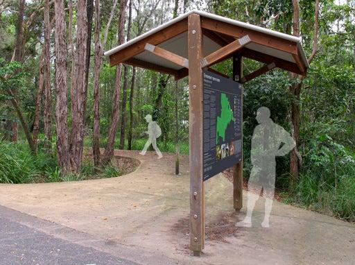
- When considering locations for a sign, avoid sites where the sign may interrupt or block a prominent view. Signs should be secondary to a natural view.
- To ensure a sign will not be obscured in future, consider the mature size of surrounding vegetation.
- For a new pathway – a luminance contrast treatment is recommended to form the sign slab and must be the full width of the path of travel.
- Textured slab treatments should be considered. See LIM Signage - Equal access – Colour and texture requirements for further guidance for when to apply.
- If a pathway/trail is less than 2.0 m wide, a slab extension or compacted surface treatment is required. This provides an area for viewing the sign while not blocking pedestrians.
- Where there is an existing or new pathway, all signs must meet Austroads minimum 500 mm safety offset from any path edge, to avoid collision with the sign while using the pathway.
- Locate signs within a garden bed where possible to avoid the sign becoming an obstacle and for maintenance operations.
- To protect trees from potential damage, all signs should be installed outside of their canopy areas (drip lines). Where this is not possible, the Project Arborist should be contacted to provide advice. See LIM Site set up (including Tree protection).
Specific signs
- All Activity entry signs are to be located so that they are visible on approach to the area.
- Fenced dog off leash area signs - Regulatory signs must be located at the entry and at the exit gates (to warn users to replace a leash).
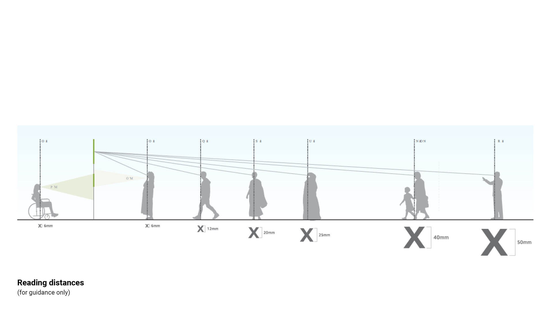
Viewing distance
Objects to be viewed up-close on a sign, require a higher resolution. In most instances, directional signs require a higher letter height than interpretive (information) signs. Viewers are more likely to spend more time and view from closer distances when reading interpretive long message signs (pedestrian entry, information/map, or interpretive signs). Short message signs, such as directional or regulatory and activity entry signs are generally read quickly and from a distance.
- Signs intended for up-close viewing by people who are standing should be centred at a height of 1.5 m.
Long message signs – require time to read and interpret the information. They require space to stand or sit in a wheelchair, while not blocking other path users.
Short message signs – requires a short time to read and interpret. They can be read while walking, riding or wheeling by, or while taking a moment to glance at the information. Space to interpret the sign is not required.
* In accordance with AS 1428.2:2015 a minimum offset of 325 mm space is required in front of a sign containing raised tactile and Braille. (Females 325 mm, Males 400 mm).
Signs intended for close viewing by people who use wheelchairs are to be centred at a height of 1227 mm to comply with AS 1428.2:1992 Design for access and mobility. (Optimum viewing height 1.2 m – 1.7 m from finished surface level).
- In accordance with AS 1428.4.2:2018 Design for access and mobility, Part 4.2 Wayfinding signs, a reading offset of 325 mm is required in front of a sign containing raised tactile and Unified English Braille Code (UEBC) Grade 1, (Females 325 mm, Males 400 mm). This space allows room for the user to interpret the content by touch.
See the following table/figures for further guidance:
- Table 3: Recommending letter heights for viewing
- Figure 12: Reading distances.
Table 3: Recommending letter heights for viewing
Viewing distance (metres) | Minimum letter height (millimetres) |
2.0 m | 6.0 mm |
4.0 m | 12 mm |
6.0 m | 20 mm |
8.0 m | 25 mm |
12 m | 40 mm |
15 m | 50 mm |
25 m | 80 mm |
35 m | 100 mm |
40 m | 130 mm |
50 m | 150 mm |
Source: AS 1428 set – Design for access and mobility. For further guidance for letter heights for different situations, refer AS 1428.2 - 17 Signs 1992. Accredited access consultant advice recommends 6.0 mm letter height from a viewing distance of 2.0 m.
Figure 12: Reading distances *ASH FIGURE TO BE UPDATED
Positioning on a path or trail network
Signs should be placed so that they create minimal visual impact on views, natural areas or culturally significant sites.
Pathways
- Interpretive (information) signs should be placed at natural and significant sites.
- Directional signs should be placed in transitional areas and at decision points to direct users to the correct route.
Trails
- For trail networks of up to 2.0 km in length, it is recommended that markers be provided at average spacing of 100 to 300 m.
- For longer trails, the above should be used as a guideline. However the trail terrain, grade and level of use will also determine the appropriate spacing of signs.
Clearances and viewing heights
General
- For all pathways, signs must comply with Austroads minimum 500 mm offset for clearance safety.
- Position signs in a planting area where possible, for ease of maintenance mowing and to conflict areas.
- Planted areas near or around a sign should comprise low plantings to retain view lines. This will ensure the sign is not obscured from a motorist or pedestrian.
- Positioning a sign on pathways or any pedestrian surface (any firm surface a person can walk or wheel on, with the exception of grass), is not recommended for the following reasons:
- Single sign posts can blend into the background and may not always been seen.
- If a sign is installed on a pathway, Tactile Ground Surface Indicator (TGSIs) are required around the base of the sign in accordance with AS 1428.4.1:2009. This is not a preferred option.
- Where a sign displays a short message, a 2.0 m pathway provides sufficient space for reading a sign which is installed 500 mm off the pathway.
- Short message sign examples are Wayfinding markers, activity entry and regulatory signs. These signs may vary for viewing heights.
- Wayfinding markers that can be touch read must be at the optimum viewing height of 1.2 m - 1.7 m above ground level.
- Activity entry sign may be installed at either 2.2, or 1.2 m above ground level.
- It may be deemed a safer solution to installed the sign at 2.2 m above ground level, to deter vandals, provide safe clearance heights or there may not be a suitably positioned garden bed for the sign to be located in. The preferred mounting height is 1.2 m, where possible. However the sign must be installed in a planted area.
- Where a sign displays a long message, an appropriately sized additional slab or compacted surface treatment area minimum 1.3 m off the pathway should be incorporated into the design. This provides space for a wheelchair or group of people, to position in front of the sign while not obstructing other path users. Long message sign examples are pedestrian entry, Map and information (trailhead) map and interpretive signs.
- These signs will be positioned using the optimum viewing height of between 1.2 m – 1.7 m above finished ground level.
See the following for further guidance:
- Table 4: Positioning guidance offsets
- Figure 15: Optimum viewing heights - vehicles
- Figure 16: Optimum viewing heights - pedestrian pathway and trail
- Figure 17: Optimum viewing heights - mountain bike trail
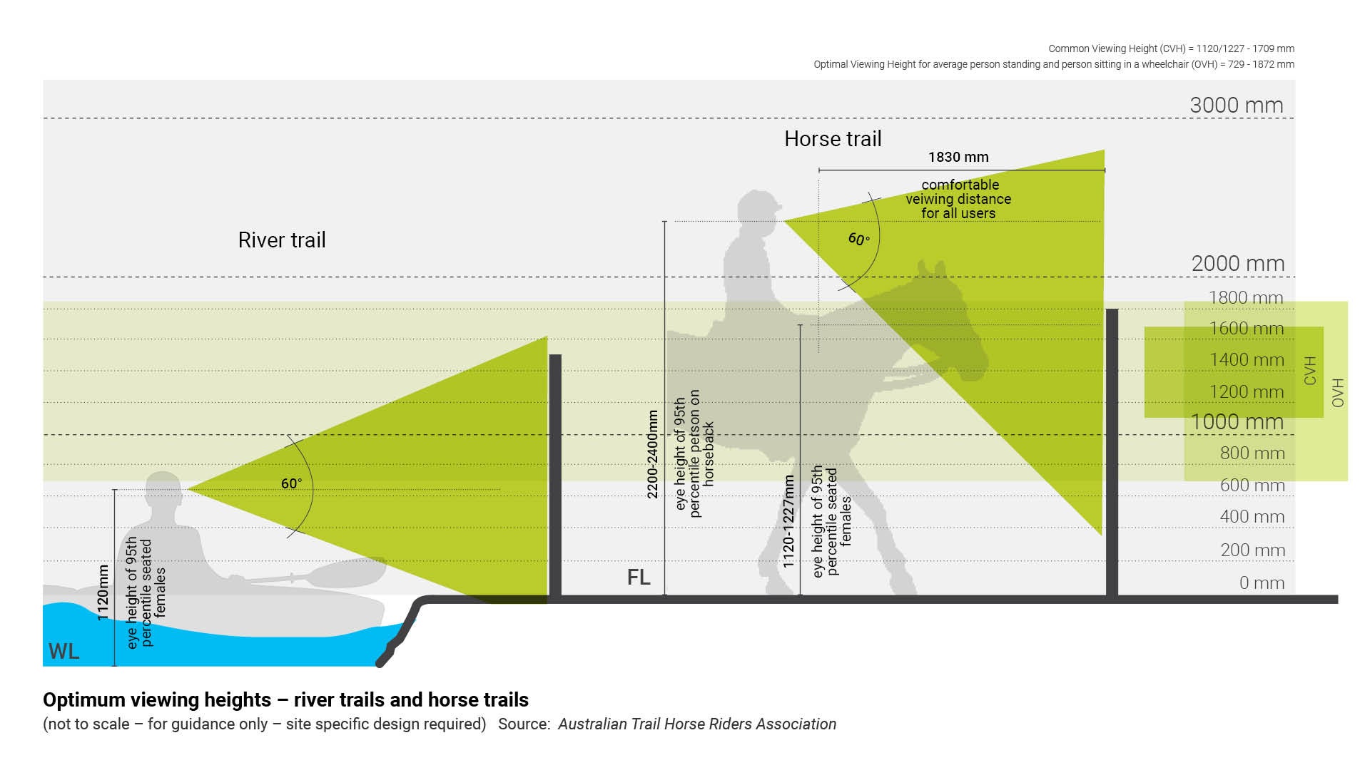
- Figure 18: Optimum viewing heights - river trails and horse trails.
Note: Consider positioning reflectors on bollards/directional markers, where they are positioned near a path, to alert users. For example, in high-speed environments, objects may appear suddenly, (when riding a bicycle) the reflectors aid in altering the rider.
Regulatory signs
- General regulatory signs must be above pedestrian and bicycle head height of 2.2 m. This height provides safe clearances as well as enabling the sign to be seen by both motorist and pedestrians. These signs must be positioned with 500 mm lateral offset from any path or trail.
- If a regulatory sign is positioned at less than the recommended height of 2.2 m above finished ground level and located in a pedestrian surface (any firm surface a person can walk or wheel on, with the exception of grass), the sign will require tactile ground surface indicators (TGSIs) around the base in accordance with AS 1428.4.1:2009.
- It is preferable to locate a regulatory sign on an entry gate (such as Dog use), however position the sign so it does not provide a potential foothold for climbing.
Interpretive signs
Currently standards and guidelines relate to road use and building Wayfinding signs. LIM Signage takes into consideration existing standards and guidelines, and includes AS 1428.4.2:2018 Design for access and mobility, Part 4.2 Wayfinding signs and recommends design outcomes tailored for open space environments.
- AS 1428.4.2:2018 requires signs to be positioned so that the message/sign face is at a comfortable viewing height for all pedestrians (includes people in wheelchairs or other mobility devices) of between 1.2 m – 1.7 m from the finished surface level. This Standard excludes mountain bike riders, horse riders and canoe/kayak users.
- Where possible, long message signs should be mounted at the optimum viewing height which is 1.2 m – 1.7 m above finished ground level.
See the following figure/tables for further guidance:
- Table 4: Positioning guidance offsets
- Figure 13: Sign offsets - typical
- Figure 14: Sign offsets - trees
- Figure 15: Optimum viewing heights - vehicles
- Figure 16: Optimum viewing heights - pedestrian pathway and trail
- Figure 17: Optimum viewing heights - mountain bike trail
- Figure 18: Optimum viewing heights - river trails and horse trails.
Table 4: Positioning guidance offsets
Embellishment | Distance from | Minimum distance | Reason |
All signs | Pathway | 500 mm minimum horizontal. | To avoid injury to pedestrians. |
All signs | Any other obstacle, such as a seat | 2.5 m horizontal | For deck mower clearance (where possible). |
Activity entry sign - Skate park | Skate facility | 5.0 m horizontal from skate surface. | For user safety while using facility. |
Activity entry sign - Skate park | Head heights of pedestrian/cyclist | 2.2 m vertical | For pedestrian/cyclist safety requirement. |
Long message signs | Pathway | 1.3 m min horizontal Optimum viewing height between 1.2 m and 1.7 m vertical. | To provide a clear zone for a wheelchair or group of people to position in front of the sign to avoid conflict with path users. |
Short message signs | Pathway |
|
|
Equal access signs (wayfinding markers) | Finished surface level | Optimum viewing height between 1.2 m and 1.7 m vertical | Optimum viewing height for people with low vision and to reach sign panel if user is required to touch to interpret sign. |
Figure 13: Sign offsets - typical
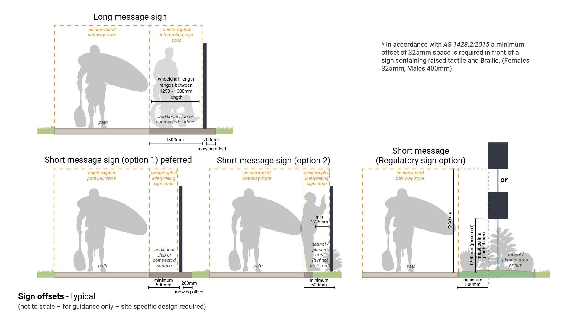
Figure 14: Sign offsets - trees
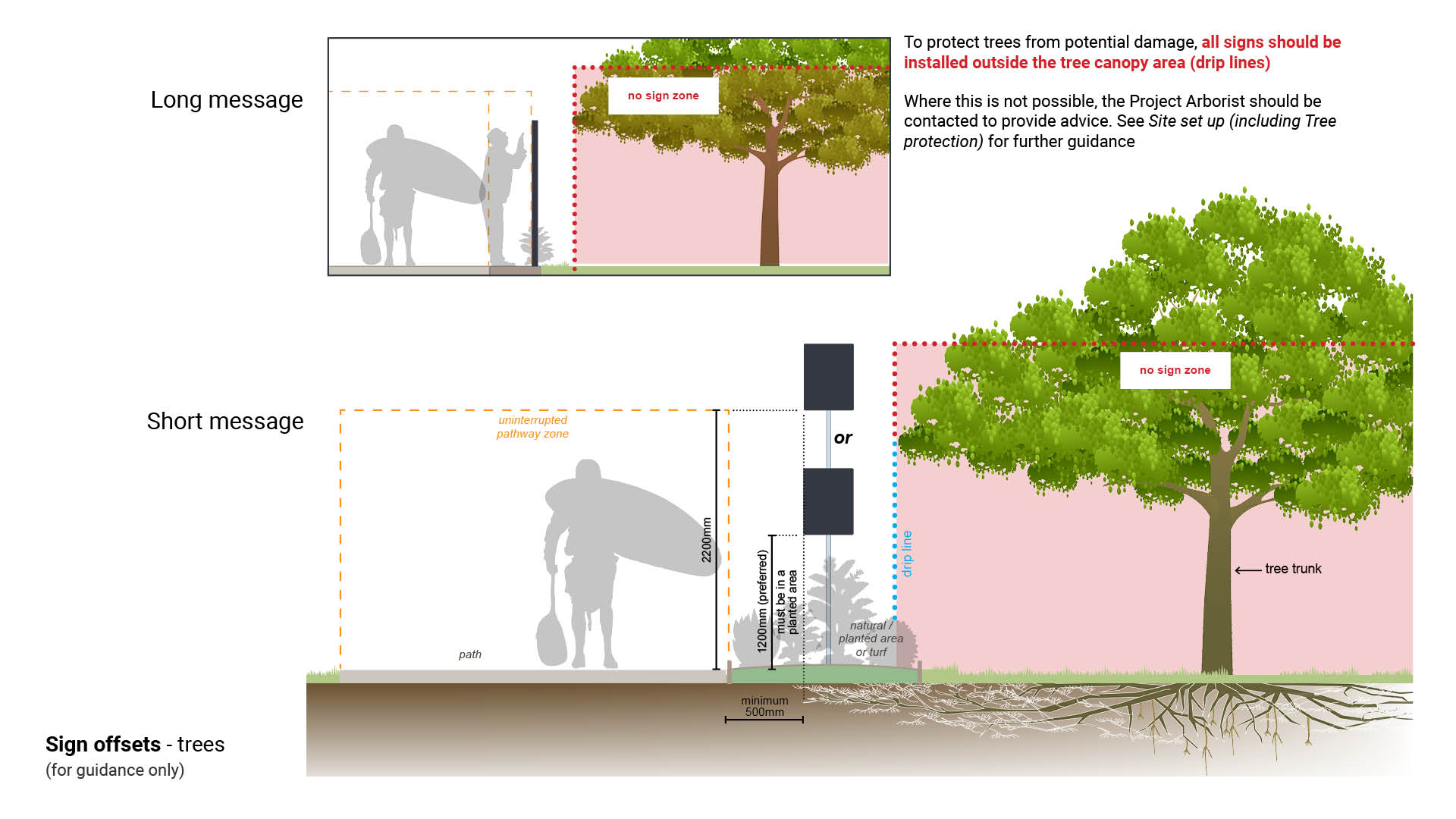
Figure 15: Optimum viewing heights - vehicles
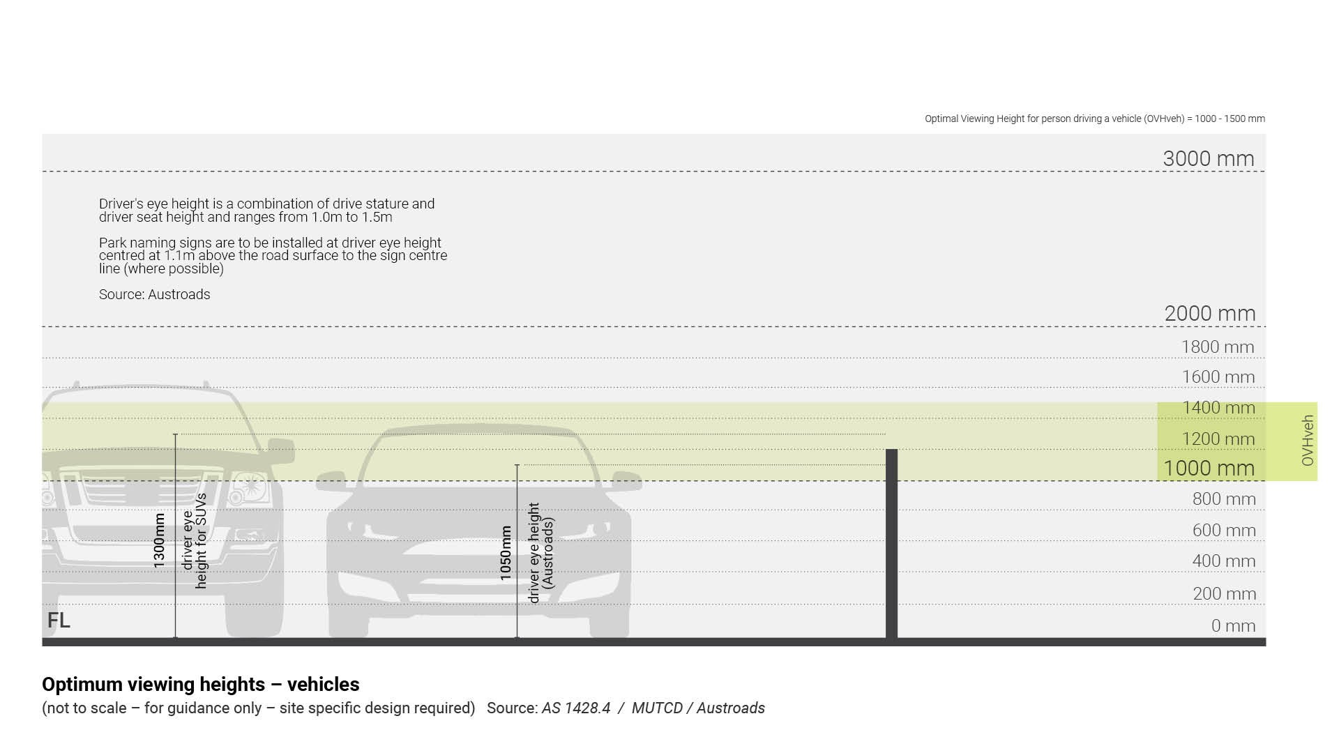
Figure 16: Optimum viewing heights - pedestrian pathway and trail
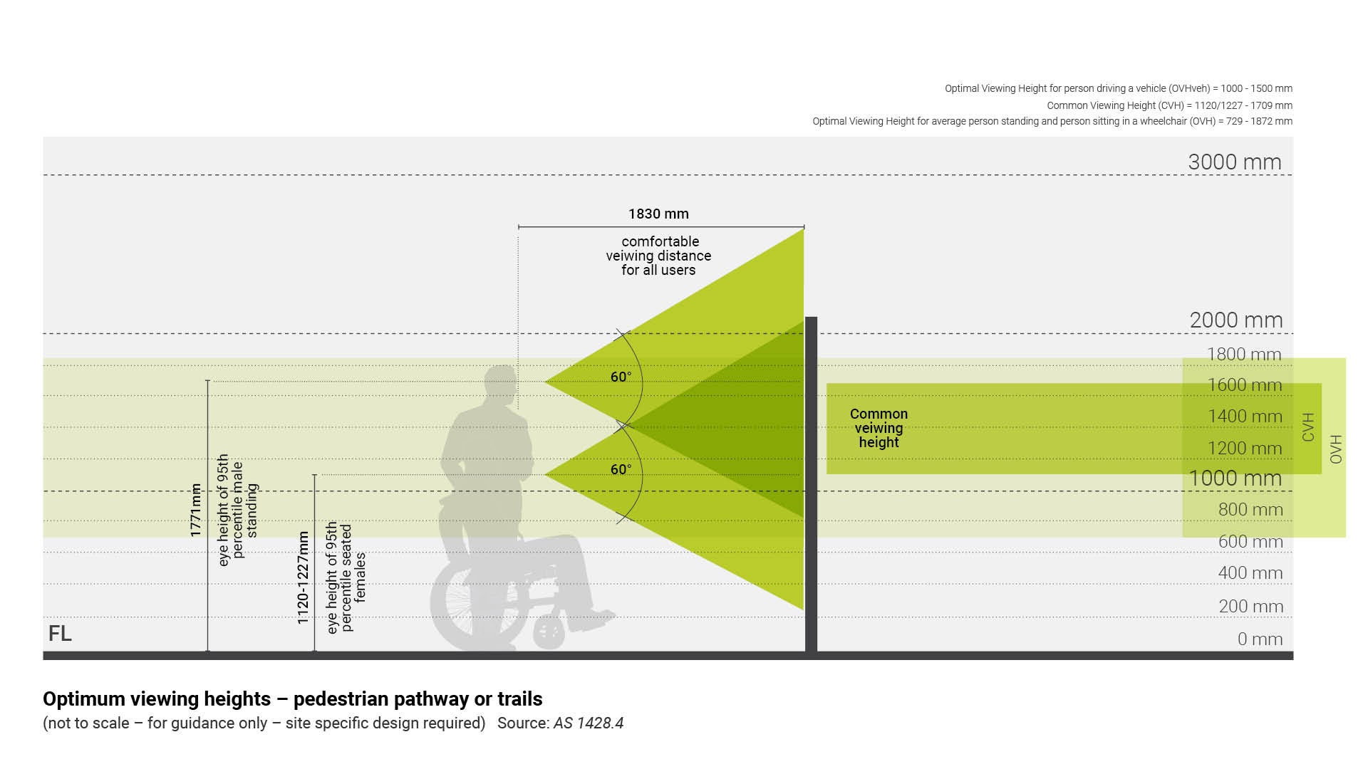
Figure 17: Optimum viewing heights - mountain bike trail
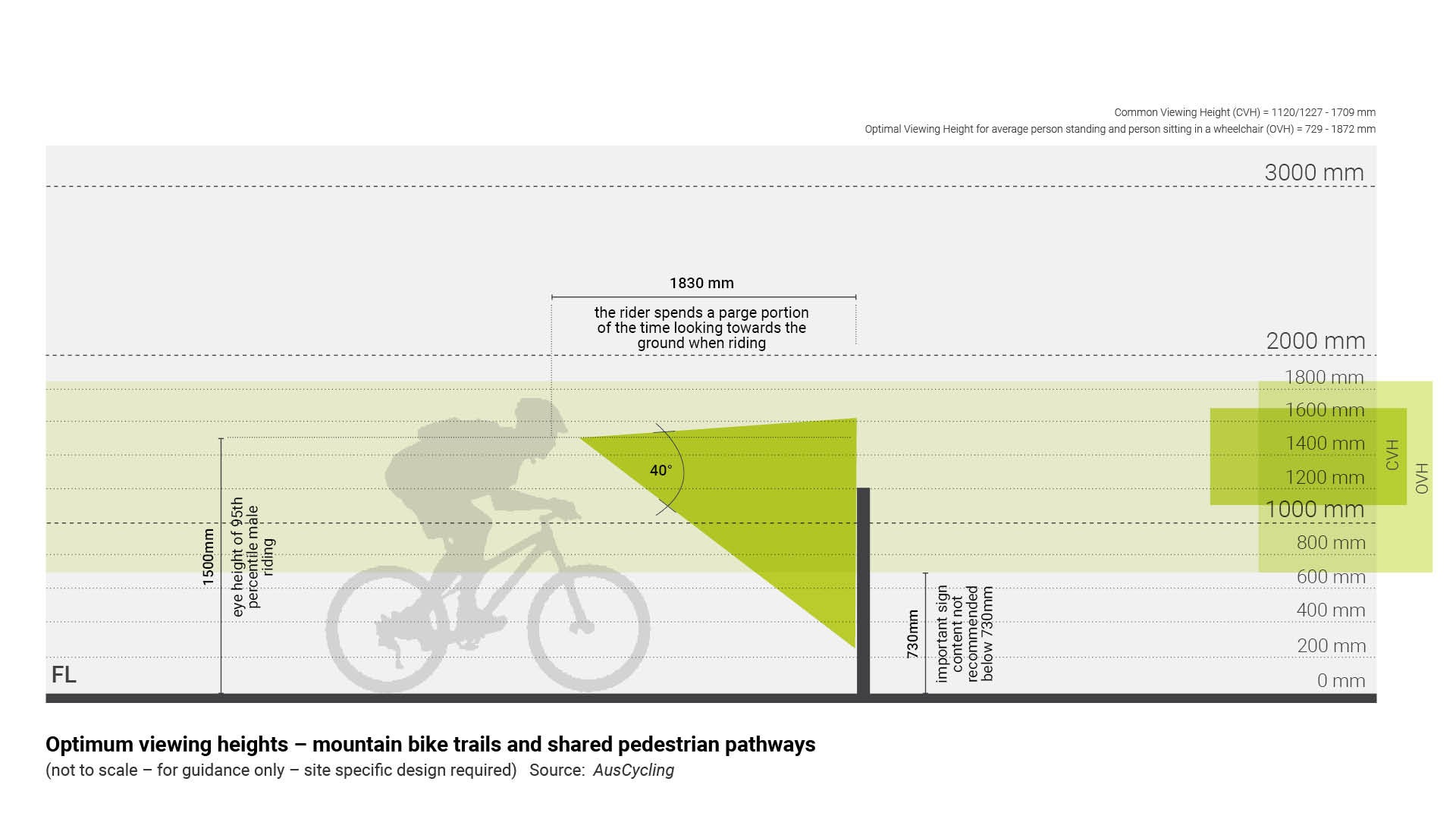
Figure 18: Optimum viewing heights - river trails and horse trails
Vehicle entry signs (Roadside signs)
Vehicle entry signs are typically installed (site centred where possible) on the property boundary and adjacent to main entrance, see Figure 19: Typical vehicle entry sign installation.
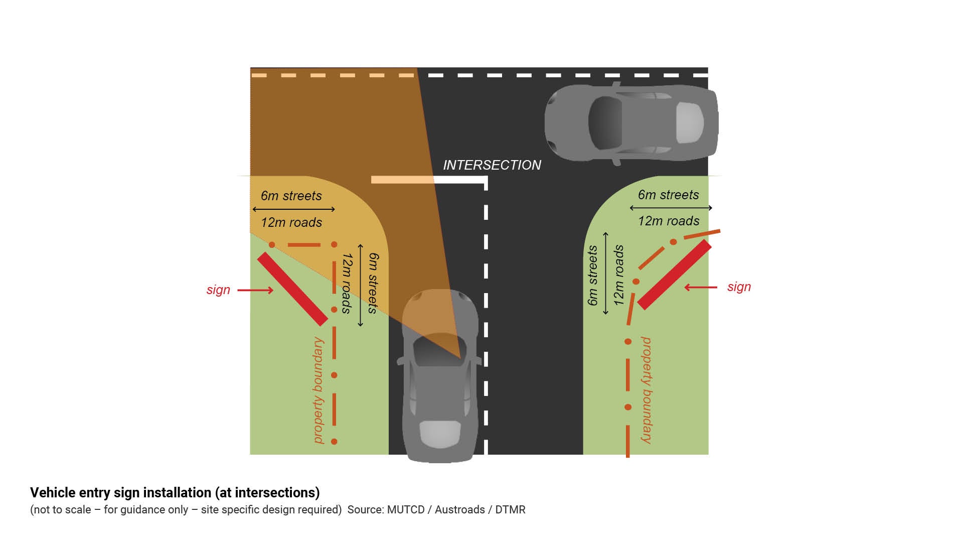
In the instance where a vehicle entry sign is installed at an intersection, see Figure 20: Vehicle entry sign installation (at intersections).
All roadside signs are to comply with the following requirements:
- Lateral placement and mounting heights:
- MUTCD Part 1:2016 – General introduction and sign illustrations.
- Clear zones
- Austroads Guide to Road Design Part 6: Roadside design, safety and barriers.
- Traffic and Road Use Manual Volume 3 - Signings and pavement marking: Part 5: Design guide for roadside signs, 2018 Department of Transport and Main Roads.
- Sight lines
- Austroads Guide to Road Design Part 3: Geometric design.
- Austroads Guide to Road Design Part 4: Intersections and crossings – general.
Note: 'Street' and 'road' definitions (road hierarchy), are sourced from Sunshine Coast Planning Scheme 2014.
Where a property boundary does not exist, the vehicle entry sign is typically aligned 4.0 m from the kerb.
Figure 19: Typical vehicle entry sign installation
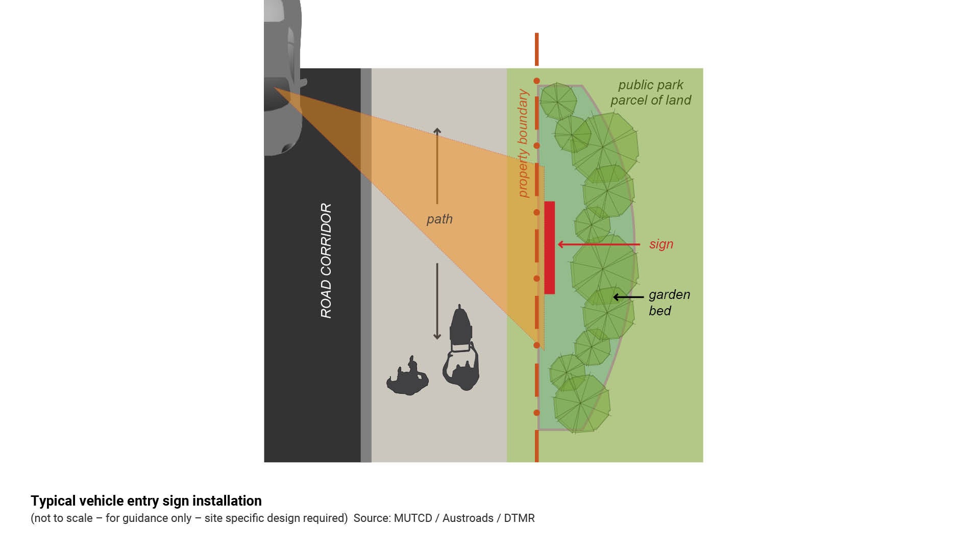
Figure 20: Vehicle entry sign installation (at intersections)
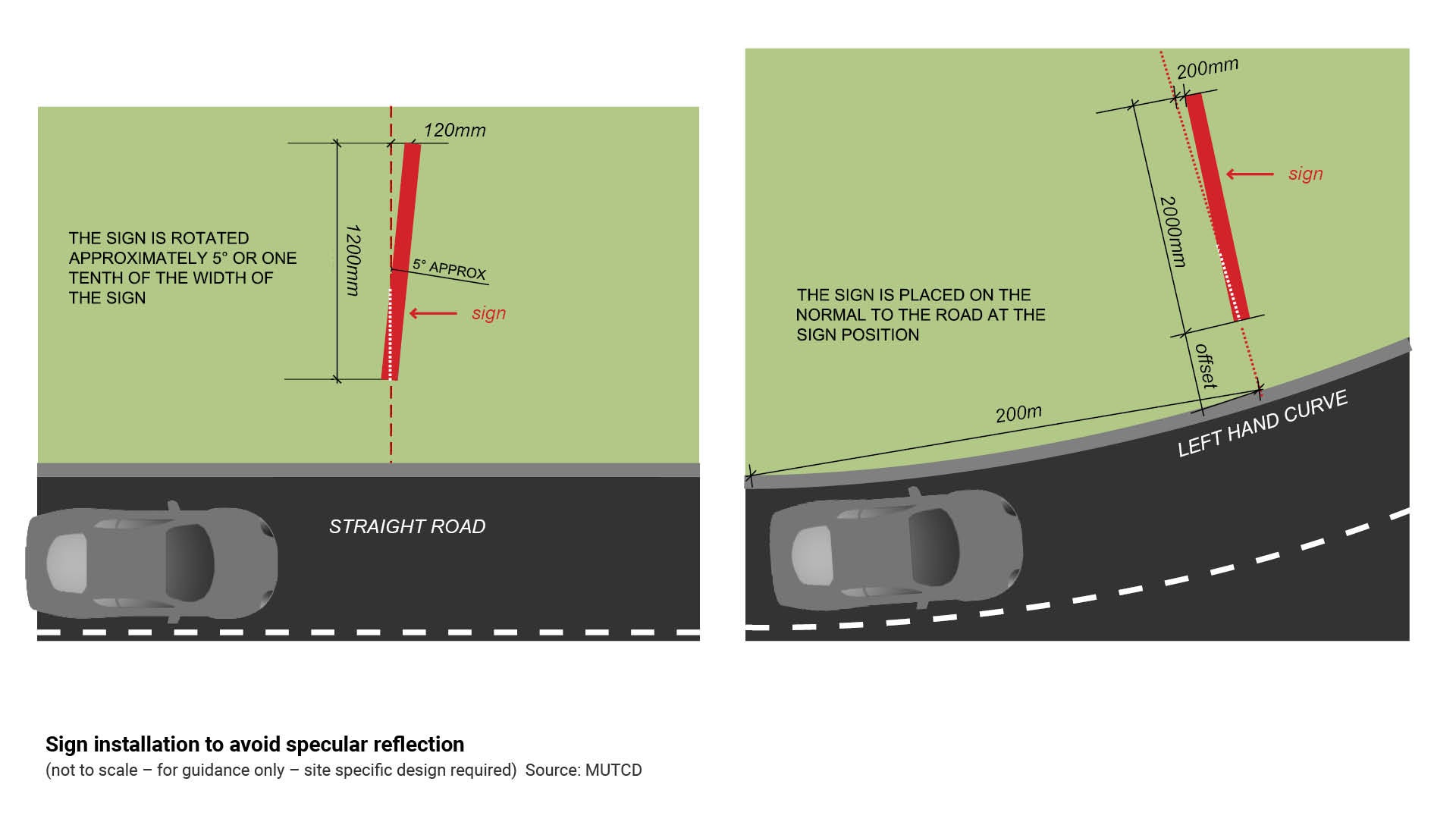
Specular reflection and sign orientation
Glare can reduce visual ability to interpret information and can cause extreme discomfort.
- Specular reflection is the reflection of a beam of light from a mirror-like surface, in which light from a single incoming direction (a ray) is reflected into a single outgoing direction.
- Where a roadside sign causes specular reflection, light rays hit the shiny sign surface and reflect back as glare to a person in a vehicle.
- This reflection of light is applicable to horizontal surfaces, vertical surfaces, angled surfaces and curved surfaces.
- The glare drivers experience at night on a wet roadway is the result of specular reflection of the beam of light from an oncoming car's headlights.
- Appropriate sign orientation can eliminate or reduce specular reflection from headlights or the sun's rays.
- To avoid specular reflection from a sign viewed by motorists, ensure that the sign is positioned as per MUTCD Part 1: General Introduction and Sign Illustrations.
See Figure 21: Sign installation to avoid specular reflection.
Note: The vehicle entry signs are NOT designed to be installed within a road reserve. The sign is designed to be installed inside the property boundary. Where the sign is installed within a road reserve, the sign must comply with the MUTCD and DTMR Guide to Roadside Signs.
Engage a Civil Engineer (internal - Design and Placemaking Services - Engineering Design Services) for site specific advice and construction documentation.
Figure 21: Sign installation to avoid specular reflection
This component is currently in development